• 1

    ..

  • 2

    ...

  • 3

    ...

Showing posts with label embedded. Show all posts

Friday, 30 January 2015

I2C Header File for AVR By Elecdude


/************************************************************************************/

 Author: ElecDude
         admin@elecdude.com        

 Please report bugs, errors, modifications, etc. Thank you

 Copyright - 2015 - ElecDude

 USAGE AND REDISTRIBUTION OF THIS SOURCE CODE IS PERMITTED PROVIDED THAT
 THE FOLLOWING CONDITIONS ARE MET:

    1. REDISTRIBUTIONS OF SOURCE CODE MUST RETAIN THE ABOVE ORIGINAL COPYRIGHT
  NOTICE AND THE ASSOCIATED DISCLAIMER, THIS LIST OF CONDITIONS AND
  THE FOLLOWING DISCLAIMER.
    2. REDISTRIBUTIONS IN BINARY FORM MUST REPRODUCE THE ABOVE COPYRIGHT
  NOTICE, THIS LIST OF CONDITIONS AND THE FOLLOWING DISCLAIMER IN
  THE DOCUMENTATION AND/OR OTHER MATERIALS PROVIDED WITH THE
  DISTRIBUTION.

 THIS IS PROVIDED WITHOUT ANY  EXPRESS OR IMPLIED WARRANTIES, INCLUDING,
 BUT NOT LIMITED TO, THE IMPLIED WARRANTIES OF MERCHANTABILITY AND FITNESS FOR
 A PARTICULAR PURPOSE ARE DISCLAIMED. TO BE USED FOR LEARNING PURPOSE ONLY.  
 IN NO EVENT SHALL THE CONTRIBUTORS OR COPYRIGHT OWNER, BE LIABLE FOR ANY DIRECT,
 INDIRECT, OR CONSEQUENTIAL DAMAGES OR ANY DAMAGES ARISING IN ANY WAY OUT OF THE
 USE OF THIS SOURCE CODE, EVEN IF ADVISED OF THE POSSIBILITY OF SUCH DAMAGE.

/*************************************************************************************/
/**************************************************************
 I2C  TWI  ROUTINES
void I2CInit();
void I2CStart();
void I2CStop();
unsigned char I2CWriteSLA(unsigned char sla);
unsigned char I2CWriteByte(unsigned char dat);
unsigned char I2CReadByte(unsigned char *data); */

#ifndef _I2C_H
#define _I2C_H

/*******************MACRO's DEFINITION******************************/
#ifndef BIT
#define BIT(x) _BV(x)
#endif

#ifndef SETBIT
#define SETBIT(x,b) x|=_BV(b);
#endif

#ifndef CLEARBIT
#define CLEARBIT(x,b) x&=~_BV(b);
#endif

#ifndef TOGGLEBIT
#define TOGGLEBIT(x,b) x^=_BV(b);
#endif

#ifndef CHECKBIT
#define CHECKBIT(x,b) (x & _BV(b))
#endif
/*******************************************************************/


#define TRUE 1
#define FALSE 0

void I2CInit()
 {
  TWBR=0x04;//F=100KHz
  TWSR|=((1<<TWPS1) | (1<<TWPS0));

  SETBIT(TWCR,TWEN)
 }

void I2CStart()
{
 TWCR=(1<<TWINT)| (1<<TWSTA)|(1<<TWEN);
 while(!(TWCR & (1<<TWINT)));

}

void I2CStop()
{
 TWCR=(1<<TWINT)| (1<<TWEN)|(1<<TWSTO);
 //while(!(TWCR & (1<<TWSTO)));

}

unsigned char I2CWriteSLA(unsigned char sla)
 {

  TWDR=sla;
  TWCR=(1<<TWEN) | (1<<TWINT);
  while(!(TWCR & (1<<TWINT)));
  if((TWSR & 0xF8)==0x18 || (TWSR & 0xF8)==0x40)
  //18 = SLA+W sent & ACK returned
  return TRUE;//40 = SLA+R sent & ACK returned
  else
    return FALSE;
}

unsigned char I2CWriteByte(uint8_t dat)
 {
  unsigned char
  TWDR=dat;

  TWCR=(1<<TWEN) | (1<<TWINT);
  while(!(TWCR & (1<<TWINT)));


  if((TWSR & 0xF8)==0x28 || (TWSR & 0xF8)==0x30)
  return TRUE; //28= Data sent, ACK returned.  30 data sent, NACK retuned
  else
    return FALSE;
}

unsigned char I2CReadByte(unsigned char *data)
 {
 
  TWCR&=(~(1<<TWEA));
 
  CLEARBIT(TWCR,TWINT)
  while(!(TWCR & (1<<TWINT)));

  if((TWSR & 0xF8)==0x50 || (TWSR & 0xF8)==0x58)
   {
  *data=TWDR; //58 = data READ & NACK retuned
return TRUE; //50 = Data READ & ACK returned
    }
  else
    return FALSE;
}

/***************************************************************************/
#endif
I2C.H

If you enjoyed this post plz let us know your views via comments.
This helps us to do much more better.
Thankyou.


interfacing DS1307 (RTC) with AVR By Elecdude


//***********************************************************************************//
 Author: ElecDude
         admin@elecdude.com        

 Please report bugs, errors, modifications, etc. Thank you

 Copyright - 2015 - ElecDude

 USAGE AND REDISTRIBUTION OF THIS SOURCE CODE IS PERMITTED PROVIDED THAT
 THE FOLLOWING CONDITIONS ARE MET:

    1. REDISTRIBUTIONS OF SOURCE CODE MUST RETAIN THE ABOVE ORIGINAL COPYRIGHT
  NOTICE AND THE ASSOCIATED DISCLAIMER, THIS LIST OF CONDITIONS AND
  THE FOLLOWING DISCLAIMER.
    2. REDISTRIBUTIONS IN BINARY FORM MUST REPRODUCE THE ABOVE COPYRIGHT
  NOTICE, THIS LIST OF CONDITIONS AND THE FOLLOWING DISCLAIMER IN
  THE DOCUMENTATION AND/OR OTHER MATERIALS PROVIDED WITH THE
  DISTRIBUTION.

 THIS IS PROVIDED WITHOUT ANY  EXPRESS OR IMPLIED WARRANTIES, INCLUDING,
 BUT NOT LIMITED TO, THE IMPLIED WARRANTIES OF MERCHANTABILITY AND FITNESS FOR
 A PARTICULAR PURPOSE ARE DISCLAIMED. TO BE USED FOR LEARNING PURPOSE ONLY.  
 IN NO EVENT SHALL THE CONTRIBUTORS OR COPYRIGHT OWNER, BE LIABLE FOR ANY DIRECT,
 INDIRECT, OR CONSEQUENTIAL DAMAGES OR ANY DAMAGES ARISING IN ANY WAY OUT OF THE
 USE OF THIS SOURCE CODE, EVEN IF ADVISED OF THE POSSIBILITY OF SUCH DAMAGE.
//***********************************************************************************//


                  FUNCTIONS IN DS1307.H
```````````````````````
    DSinit();        To initialise DS1307 RTC chip

DSWriteTime(h, m, s); To write time hr, min, sec to RTC

    DSReadTime(&h, &m, &s); To read time hr, min, sec from RTC

    DSWriteDate(d, m, y); To write date to RTC

    DSReadDate(&d, &m, &y); To read date from RTC
 
    DSReadDay(&dy);     To read day from RTC

    DSWriteDay(dy); To write day to RTC
***********************************************************/

#ifndef _ds1307_H
#define _ds1307_H
#include "I2C.h"


//declare variables for hour, minutes, seconds, day, date, month & year.
unsigned char h=0,m=0,s=0; //comment these lines if defined in Main.c
unsigned char dy=0,dd=0,mm=0,yy=0; //comment these lines if defined in Main.c

/*_________________________________________________________________________
                   DECLARATION FOR DS1307                   */
#define DS_R 0xD1   //7 bit SLA + 1(read bit)
#define DS_W 0xD0 //7 bit SLA + 0(write bit)

//DS1307 RTC Registers addresses....
#define secr   0x00
#define minr   0x01
#define hrr 0x02
#define dayr   0x03
#define dater 0x04
#define monr   0x05
#define yrr 0x06
#define conr 0x07
/*_________________________________________________________________________*/
// DSWrite(addr1,data1);
// To write 'data1' in the 'addr1' location
unsigned char DSWrite(unsigned char addr,uint8_t data)
{
//_delay_us(500);
  I2CStart();

  if(! (I2CWriteSLA(DS_W)) )//Select device
return FALSE;

  if(! (I2CWriteByte(addr)) )//select destn. register
return FALSE;

  if(! (I2CWriteByte(data)) )//write data
return FALSE;
  I2CStop();
  return TRUE;
}

// DSRead(addr1,&data1);
// To data 'data1' from the 'addr1' location
unsigned char DSRead(unsigned char addr,unsigned char *data)
{
  I2CStart();
  if(! (I2CWriteSLA(DS_W)) )//select device
return FALSE;
  if(! (I2CWriteByte(addr)) )//select register
return FALSE;

//_______________Send Repeat start for read_____________
  I2CStart();

  if(! (I2CWriteSLA(DS_R)) )// select device in MASTER READ mode
return FALSE;
  if(! (I2CReadByte(data)) )//read data form device
return FALSE;

  I2CStop();
  return TRUE;
}
/*_________________________________________________________________________*/
// DSinit();
        // To initialise DS1307 RTC chip
void DSinit()
{
unsigned char x;
DSRead(secr,&x);
x&=(~(1<<CH)); //Clear CH Bit
DSWrite(secr,x);

x=0x10;
DSWrite(conr,x);//enable out @ 1Hz
}

// DSWriteTime(h, m, s)
// To write time hr, min, sec to RTC
DSWriteTime(unsigned char h, uns
igned char m, unsigned char s)
{
DSWrite(secr,s);
DSWrite(minr,m);
DSWrite(hrr,h);
}

// DSReadTime(&h, &m, &s)
// To read time hr, min, sec from RTC
DSReadTime(unsigned char *h, unsigned char *m, unsigned char *s)
{
DSRead(secr,&s);
DSRead(minr,&m);
DSRead(hrr,&h);
}

// DSWriteDate(d, m, y)
// To write date to RTC
DSWriteDate(unsigned char dd, unsigned char mm, unsigned char yy)
{
DSWrite(dater,dd);
DSWrite(monr,mm);
DSWrite(yrr,yy);
}
// DSReadDate(&d, &m, &y)
// To read date from RTC
DSReadDate(unsigned char *h, unsigned char *m, unsigned char *s)
{
DSRead(dater,&dd);
DSRead(monr,&mm);
DSRead(yrr,&yy);
}

// DSReadDay(&dy)
// To read day from RTC
DSReadDay(unsigned char *dy)
{
DSRead(dayr,&dy);
}
// DSWriteDay(dy)
// To write day to RTC
DSWriteDay(unsigned char dy)
{
DSWrite(dayr,dy);
}

#endif
DS1307.H 

Please follow this link for I2C header File 

If you enjoyed this post plz let us know your views via comments.
This helps us to do much more better.
Thankyou.


Thursday, 14 August 2014

Renesas eclipse embedded studio


Renesas eclipse embedded studio, known as e² studio, is a complete development and debug environment based on the popular Eclipse CDT project. Essentially open source, the Eclipse CDT covers build (editor, compiler and linker control) as well as debug phase based on an extended GDB interface


Features


Memory Usage
Visual Expressions
Integrated Code Generation
Eclipse CDT Editor


Target Devices


e² studio has been developed to support the key promotion families of Renesas controllers:
  • RL78 Family
  • RX Family
  • RH850 Family*
  • SuperH Family (SH-2 and SH-2A)
As new devices are released from Renesas, e² studio can easily be updated to add the necessary support files and debugger extensions.
* Note, The working sample for RH850 is supported. (Debug support only)

To know More click here


Saturday, 26 April 2014

FREQUENCY MEASUREMENT USING AVR ATMEGA8

     Often frequency measurement is needed, but one cannot afford a DSO or an appropriate meter for that. So we have designed it in AVR microcontroller which is easily available and much easier to program.

    This frequency measurement uses Input Capture module in Timer1 via ICP pin PB0. For ease of programming, we have designed a low frequency measurement for frequencies lesser than 1KHz, but can be increased upto several 100KHz, through prescalar.

       The circuit diagram is

Monday, 7 April 2014

SY-HS 220 Humidity Sensor Interfacing with AVR Atmega (8/16/32)

SY HS220 is the Relative Humidity Sensor with near linear output reference to relative humidity.
Its opereating RH percentage is 30-90% with Output Voltage range 990-2970mV.

Here we've interfaced SY HS220 with AVR ATMEGA8 microcontroller and display %RH in LCD.

Circuit Diagram:

undefined
ElecDude: HS220 AVR Circuit
Code:
/* ~ ~ ~ ~ ~ ~ ~ ~ ~ ~ ~ ~ ~ ~ ~ ~ ~ ~ ~ ~ ~ ~ ~ ~ ~ ~ ~ ~ ~ ~ ~ ~ ~ ~ ~ ~ ~
Author: ElecDude
         admin@elecdude.com      

Copyright - 2014 - ElecDude

DISCLAIMER:

 THIS SOURCE FILE MAY BE USED AND DISTRIBUTED WITHOUT      
 RESTRICTION PROVIDED THAT THIS COPYRIGHT STATEMENT IS NOT 
 REMOVED FROM THE FILE AND THAT ANY DERIVATIVE WORK CONTAINS
 THE ORIGINAL COPYRIGHT NOTICE AND THE ASSOCIATED DISCLAIMER.

 This is provided without any  express or implied warranties,
 including, but not limited  to, the implied warranties of merchantability
 and fitnessfor a particular purpose. FOR EDUCATIONAL PURPOSE ONLY.

~ ~ ~ ~ ~ ~ ~ ~ ~ ~ ~ ~ ~ ~ ~ ~ ~ ~ ~ ~ ~ ~ ~ ~ ~ ~ ~ ~ ~ ~ ~ ~ ~ ~ ~ ~ ~ ~ ~
                          SY-HS 220 Humidity Sensor
     Input voltage = 5.0V                    Operating Temperature = 0-60'C
    Operating Humidity = 30-90% RH        Output Voltage = 990-2970mV
    Std.output = 1.98V   at 25`C 60%RH    Accuracy = +/-5%RH  at 25'C & 60%RH

Normal Values
%RH   mV
 30      990
 40     1300
 50     1650
 60     1980
 70     2310
 80     2640
 90     2970

    V-RH RATIO = 0.30301    by linear slope
    %RH = RATIO * Vout

ADC    Vadc = Vref * adcval/1024

If Vref= Vcc= 4.96, then
    %RH= Vout * 0.30301
       = Vref * adcval/1024 * 0.30301
    %RH= 0.0001467 * adcval
~ ~ ~ ~ ~ ~ ~ ~ ~ ~ ~ ~ ~ ~ ~ ~ ~ ~ ~ ~ ~ ~ ~ ~ ~ ~ ~ ~ ~ ~ ~ ~ ~ ~ ~ ~ ~*/


#define F_CPU 1000000UL
/*****************MACRO's DEFINITION*********************************/
#ifndef BIT
#define BIT(x)    _BV(x)
#endif
#ifndef SETBIT
#define SETBIT(x,b)     x|=_BV(b);
#endif
#ifndef CLEARBIT
#define CLEARBIT(x,b)     x&=~_BV(b);
#endif
#ifndef TOGGLEBIT
#define TOGGLEBIT(x,b)     x^=_BV(b);
#endif
#ifndef CHECKBIT
#define CHECKBIT(x,b)     (x & _BV(b))
#endif

#include <avr/io.h>
#include <util/delay.h>
void WaitMs(unsigned int ms) // waits (pauses) for ms milliseconds
{
    unsigned int m;
    for(m=0;m<=ms/10;m++)
    {
        _delay_ms(10);
    }
}

#include "ADCHEAD.H"
#include "lcd.c"

#define PRT PIND
#define sw1 0
#define sw2 1
#define sw3 2
#define TIME 100
register unsigned char i asm("r17");

#define R 0.148
unsigned char count=0x00,chng=1;
unsigned int val,th;
char d2[]="00.0%";
void UpdateVal()
{
    float rh;
    uint16_t x;
    rh=R*val; //xx.y
    x=rh*10; //xxy
    d2[3]= (x%10) | 0x30;//ones
    x/=10;
    d2[1]= (x%10) | 0x30;//tens
    x/=10;
    d2[0]= (x%10) | 0x30;//hund
}

int main()
{
      CLEARBIT(DDRC,4)//set as i/p for adc
    CLEARBIT(DDRC,5)
    DDRD=0xF8;//enable PD as i/p & en pull ups
    PORTD=0x07;
    SETBIT(DDRB,7)
    SETBIT(PORTB,7)
   
    _delay_ms(10);
    LCD_init(COFF);
    _delay_ms(100);
    LCD_putsPXY(3,0,"Welcome to");
    LCD_putsPXY(4,1,"ElecDude");
    ADC_init();
   
    WaitMs(800);//wait for some time to initialise
    LCD_clear();
    SetCH(0x05); //PC5=HS220's Vout
    val=0;i=0;
    LCD_putsPXY(0,0,"Relativ Humidity");
    while(1)
        {
            TOGGLEBIT(PORTB,7)
            val+=ADC_readcurch();
            i++;       
            if(i==4)
             {
                val=val/4;
                UpdateVal();
                LCD_putsXY(5,1,d2);
                i=0; val=0; //clear after update
             }// endof if(i==4)
         WaitMs(200);
        }//end of while
return 0;
}

ADCHEAD.H

#define ADC_ENABLE()         SETBIT(ADCSRA,ADEN)        //Macro to enable ADC Module.
#define ADC_DISABLE()         ADCSRA &= 0x7F            //Macro to disable ADC MOdule.
#define ADC_START_CONV()     SETBIT(ADCSRA,ADSC)        //Macro to start ADC conversion.
//#define ADC_STOP_CONV()        CLEARBIT(ADCSRA,ADSC)    //Macro to stop ADC conversion.
#define ADC_CLEAR_ADIF()     CLEARBIT(ADCSRA,ADIF)        //Macro to clear ADC Interrupt flag.

#define VREF 4.96        //Defines the VREF used.
/*            Value in Volts = ADC Value * (VREF/1024)
            ADC resolution = 4.96/1024 = 4.84mV            */
/*************************************************************************************
                    ACD initialization routine
*/

void ADC_init(void)    //Function used to initialise the ADC Module.
{
    ADMUX = 0x45;         //Select the channel ADC5, AVcc, ADC right adjust, chn=0-5
    ADCSRA = 0x83;     // 

    _delay_ms(150);     //Provide adequate delay to initialise the analog circuitry.

}


#define ADC_read() ADC
/* To read & return adc value from a channel (chn=> 0 to 5)    */
#define SetCH(chn) ADMUX=(ADMUX & 0xF0) | (chn & 0x07)
                                        // 07- because Max 5 channels for ATM8
int ADC_readch(unsigned char chn)       
{
    ADMUX= (ADMUX & 0xF0) | (chn & 0x0F);
    ADC_CLEAR_ADIF(); //Clear ADC Interrupt Flag
    ADC_START_CONV(); //Start ADC Conversion.
    while(!(CHECKBIT(ADCSRA,ADIF)));//wait for conversion complete
    return(ADC_read());//----read values & return
}

/* TO READ FROM CURRENTLY SET CHANNEL IN ADCMUX.
    Note: This function doesn't change the ADC channel & uses the value set in ADCMUX
          So set the required channel before calling this function   */

int ADC_readcurch()       
{
    ADC_CLEAR_ADIF(); //Clear ADC Interrupt Flag
    ADC_START_CONV(); //Start ADC Conversion.
    while(!(CHECKBIT(ADCSRA,ADIF)));//wait for conversion complete
    return(ADC_read());//----read values & return
}

/***/


Output:

Thursday, 7 November 2013

MAX7219 7 Seg LED interfacing with AVR ATMEGA 8/16/32/328

        In previous post, we have seen in detail about MAX7219 & its registers and how to configure it. Now here we present an example of using MAX7219 with 7 segment LED interfacing with AVR ATmega family microcontroller.


LIST OF FUNCTIONS IN FOR  MAX7219  

  Shuts down or normals the Display (DON/DOFF)   MX7219_shutdown(sd)  
  Test the display or normal operation (NORM/TEST) MX7219_display_test(dt)
  Sets the Digit Brightness value (0x01 to 0x0F) MX7219_set_brightness(brightness)

  Set scan limit MX7219_set_scanupto(digit)

  Decode settings MX7219_set_decode(de)
        de -> NONE=0x00,  D0=0x01,  D0-D3=0x0F,  D0-D7=0xFF
  DECODE NONE MX7219_set_decode_NONE()

  Clear all 8 segments MX7219_clear_disp()
  Blanks all 8 segments MX7219_blank_bcd_disp()
  Display a BCD digit MX7219_dispbcd(pos,dat)
  Display a Matrix MX7219_disp_matrix(mat,size,st)
  Initialize 7219 MAX7219_init()


Here is the circuit diagram interfacing AVR ATmega8 with MAX7219 to 7 Seg LED


The Proteus simulation output for the project is shown below,


Click here to download the AVR Project file with C code & MAX7219 Header file.


If you enjoyed this post plz let us know your views via comments.
This helps us to do much more better.
Thankyou.

Saturday, 26 October 2013

About MAX7219 LED Display Dot-matrix Display Driver - Data Format - Register Map - Programming


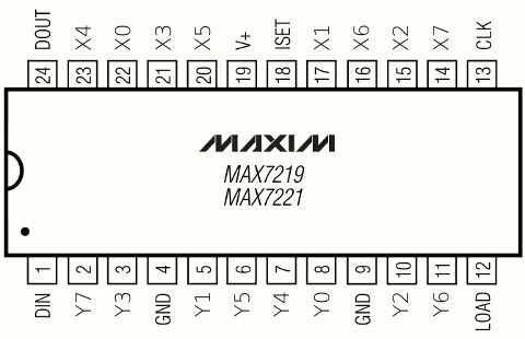
                The MAX7219 chip from maxim is a powerful serial input/output common-cathode display driver that interfaces microcontroller to 7-segment numeric LED displays of up to 8 digits and a 8x8 dot-matrix displays. The pindiagram of MAX7219 is (for MAX7221, pin 12 is CS_bar)

MAX7219
Typical application circuit is


Many MAX7219 can be cascaded serially through DOUT pin of one IC to DIN of the another, but with common clock and load connections. 

        It needs only 3 wires to interface with the microcontroller or microprocessor namely, CLK, LOAD and DIN. It has a build-in BCD (binary code decimal) decoder and a brightness control. It is easy to enable or disable the BCD decoder through the registers. Although the main function is to drive the 8-Digits seven segment LED display but because it also capable to drive an individual LED segment i.e. segment A to segment G and DP (decimal point), by disabling the decoder.

         The MAX7219 chip has 16-bit registers divided into two ADDRESS and DATA each of 8 bit size. The data format for programming is
at the negative edge of CLK, the DIN appears at DOUT for cascading

                In order to send a command to the MAX7219 chip, first we need send the 8-bits address and next we send the 8-bits data. It uses D8-D11 as address to map 14 registers. The register map is //               

           //Max7219 Command registers Address
               DECODE         0x09      // Decode mode register Address
               INTENSITY     0x0A      // Intensity register Address
               SCAN_LIMIT   0x0B      // Scan limit register Address
               SHUTDOWN   0x0C      // Shutdown register Address
               DISPLAY_TEST  0x0F     // Display test" register Address
               NOP  0x00
               D0  0x01
               D1  0x02
               D2  0x03
               D3  0x04
               D4  0x05
               D5  0x06
               D6  0 x07
               D7  0x08

          The data byte should be proceeded by the address byte.
       The segment current is set by an external resistor (Rset) connected to pin 18 and VCC. The intensity can be controlled by software using Intensity register, setting values 1 (min) to 15 (max).

          The Shutdown mode turns off all segment drives if its data is 0x00 and normal op if 0x01.

          The Display test mode turns on all segment drives if its data is 0x01 and normal op if 0x00.

        The Decode register is used to enable BCD decoder for the digits. the values are NONE=0x00,  D0=0x01,  D0-D3=0x0F,  D0-D7=0xFF

        The Scan limit register is used to set the number of used digits. 

      The same principle is also apply to other important MAX7219 chip commands such as activate from the shutdown mode (normal operation), use BCD decode (code B) mode, scanning limit (scanning digit 0 to 7), and adjusting the seven segment LED digit intensity please refer to the Maxim MAX7219 datasheet for the complete explanation.


          Comming soon: Interfacing MAX7219 with AVR for 7seg LEDs & later 8x8 dot matrix displays... Stay Tuned. Dont miss it.


If you have any doubts/need any clarification plz let us know your views via comments or mail us through   admin@elecdude.com
This helps us to do much more better.

Thankyou.

Thursday, 24 October 2013

FONT MAP HEADER FOR GLCD DOT-MATRIX DISPLAYS - AVR PIC

        The GLCDs & Dot-Matrix displays cannot directly display ASCII characters. And needs to be displayed bit-by-bit or byte-by-byte in specific manner to display the required character. Here are the font memory map that resides in program memory of the controller & then read and displayed sequentially to create a particular ASCII character.


        Font Map or font header file for GLCD & Dot-Matrix displays for AVR microcontrollers, also supports PIC, etc (GCC Complier). The font display sizes are 5x7 & 5x8 pixels.

        The header file contains the format for reading & displaying the ASCII character.

Click to download the font header file.
Font_5x7.h   Specially for 8x8 Dot-Matrix Display using 7219
Font_5x8.h  Specially for GLCD from Osama's Lab
Font_5x7.h   for GLCD


If you enjoyed this post plz let us know your views via comments.
This helps us to do much more better.
Thankyou.


Friday, 4 October 2013

serial communication protocol I²C vs SPI: is there a winner?

                      Serial Communication Protocol                                

 I²C vs SPI: is there a winner?

Let’s compare I²C and SPI on several key protocol aspects:

- Bus topology / routing / resources:
I²C needs 2 lines and that’s it, while SPI formally defines at least 4 signals and more, if you add slaves. Some unofficial SPI variants only need 3 wires, that is a SCLK, SS and a bi-directional MISO/MOSI line. Still, this implementation would require one SS line per slave. SPI requires additional work, logic and/or pins if a multi-master architecture has to be built on SPI. The only problem I²C when building a system is a limited device address space on 7 bits, overcome with the 10-bits extension.
From this point of view, I²C is a clear winner over SPI in sparing pins, board routing and how easy it is to build an I²C network.

- Throughput / Speed:
If data must be transferred at ‘high speed’, SPI is clearly the protocol of choice, over I²C. SPI is full-duplex; I²C is not. SPI does not define any speed limit; implementations often go over 10 Mbps. I²C is limited to 1Mbps in Fast Mode+ and to 3.4 Mbps in High Speed Mode – this last one requiring specific I/O buffers, not always easily available.

- Elegance:
It is often said that I²C is much more elegant than SPI, and that this last one is a very ‘rough’ (if not ‘dumb’) protocol. Actually, we tend to think the two protocols are equally elegant and comparable on robustness.
I²C is elegant because it offers very advanced features – such as automatic multi-master conflicts handling and built-in addressing management – on a very light infrastructure. It can be very complex, however and somewhat lacks performance.
SPI, on the other hand, is very easy to understand and to implement and offers a great deal of flexibility for extensions and variations. Simplicity is where the elegance of SPI lies. SPI should be considered as a good platform for building custom protocol stacks for communication between ICs. So, according to the engineer’s need, using SPI may need more work but offers increased data transfer performance and almost total freedom.
Both SPI and I2C offer good support for communication with low-speed devices, but SPI is better suited to applications in which devices transfer data streams, while I²C is better at multi master ‘register access’ application.
Used properly, the two protocols offer the same level of robustness and have been equally successful among vendors. EEPROM (Electrically-Erasable Programmable Read-Only Memory), ADC (Analog-to-Digital Converter), DAC (Digital-to-Analog Converter), RTC (Real-time clocks), microcontrollers, sensors, LCD (Liquid Crystal Display) controllers are largely available with I²C, SPI or the 2 interfaces.

Conclusions.

        In the world of communication protocols, I²C and SPI are often considered as ‘little’ communication protocols compared to Ethernet, USB, SATA, PCI-Express and others, that present throughput in the x100 megabit per second range if not gigabit per second. Though, one must not forget what each protocol is meant for. Ethernet, USB, SATA are meant for ‘outside the box communications’ and data exchanges between whole systems. When there is a need to implement a communication between integrated circuit such as a micro-controller and a set of relatively slow peripheral, there is no point at using any excessively complex protocols. There, I²C and SPI perfectly fit the bill and have become so popular that it is very likely that any embedded system engineer will use them during his/her career.


If you enjoyed this post plz let us know your views via comments.
This helps us to do much more better.
Thankyou.

Thursday, 8 August 2013

TRANSISTOR CODES AND CHOOSING by WWW.ELECDUDE.COM

TRANSISTOR CODES
There are three main series of transistor codes used in the UK:

* Codes beginning with B (or A), for example BC108, BC478
   
    The first letter denotes the material
                                   B - SILICON
                                   A - GERMANIUM

   The second letter denotes the type of the transistor
                                   C-LOW PWER AUDIO FREQUENCY
                                   D-HIGH POWER AUDIO GREQUENCY
                                   F-LOW POWER HIGH FREQUENCY
                                   The rest of the code identifies the particular transistor

         There is no obvious logic to the numbering system. Sometimes a letter is added to the end (eg BC108C) to identify a special version of the main type, for example a higher current gain or a different case style. If a project specifies a higher gain version (BC108C) it must be used, but if the general code is given (BC108) any transistor with that code is suitable.

*Codes beginning with TIP, for example TIP31A

           TIP refers to the manufacturer: Texas Instruments Power transistor. The letter at the end identifies versions with different voltage ratings.

* Codes beginning with 2N, for example 2N3053
    
           The initial '2N' identifies the part as a transistor and the rest of the code identifies the particular transistor. There is no obvious logic to the numbering system.


Choosing a transistor

         Most projects will specify a particular transistor, but if necessary you can usually substitute an
equivalent transistor from the wide range available. The most important properties to look for
are the maximum collector current IC and the current gain hFE. To make selection easier most
suppliers group their transistors in categories determined either by their typical use or
maximum power rating.
         To make a final choice you will need to consult the tables of technical data which are normally
provided in catalogues. They contain a great deal of useful information but they can be difficult
to understand if you are not familiar with the abbreviations used. The table below shows the
most important technical data for some popular transistors, tables in catalogues and reference
books will usually show additional information but this is unlikely to be useful unless you are
experienced. The quantities shown in the table are explained below.

NPN transistors
Code Structure Case style IC max. VCE max. hFE min. Ptot max. Category (typical use) Possible substitutes
BC107 NPN TO18 100mA 45V 110 300mW Audio, low
power BC182 BC547
BC108 NPN TO18 100mA 20V 110 300mW
General
purpose, low
power
BC108C BC183
BC548
BC108C NPN TO18 100mA 20V 420 600mW
General
purpose, low
power
BC109 NPN TO18 200mA 20V 200 300mW
Audio (low
noise),low
power
BC184 BC549
BC182 NPN TO92C 100mA 50V 100 350mW
General
purpose, low
power
BC107 BC182L
BC182L NPN TO92A 100mA 50V 100 350mW
General
purpose, low
power
BC107 BC182
BC547B NPN TO92C 100mA 45V 200 500mW Audio, low
power BC107B
BC548B NPN TO92C 100mA 30V 220 500mW

General
purpose, low
power
BC108B
BC549B NPN TO92C 100mA 30V 240 625mW
Audio (low
noise), low
power
BC109
2N3053 NPN TO39 700mA 40V 50 500mW
General
purpose, low
power
BFY51
BFY51 NPN TO39 1A 30V 40 800mW
General
purpose,
medium power
BC639
BC639 NPN TO92A 1A 80V 40 800mW
General
purpose,
medium power
BFY51
TIP29A NPN TO220 1A 60V 40 30W
General
purpose, high
power
TIP31A NPN TO220 3A 60V 10 40W
General
purpose, high
power
TIP31C TIP41A
TIP31C NPN TO220 3A 100V 10 40W
General
purpose, high
power
TIP31A TIP41A
TIP41A NPN TO220 6A 60V 15 65W
General
purpose, high
power
2N3055 NPN TO3 15A 60V 20 117W
General
purpose, high
power
Please note: the data in this table was compiled from several sources which are not entirely consistent!
Most of the discrepancies are minor, but please consult information from your supplier if you require precise
data.
PNP transistors
Code Structure Case
style
IC

max.
VCE
max.
hFE
min.
Ptot
max.
Category
(typical
use)
Possible
substitutes


BC177 PNP TO18 100mA 45V 125 300mW Audio, low
power BC477
BC178 PNP TO18 200mA 25V 120 600mW
General
purpose, low
power
BC478
BC179 PNP TO18 200mA 20V 180 600mW
Audio (low
noise), low
power
BC477 PNP TO18 150mA 80V 125 360mW Audio, low
power BC177
BC478 PNP TO18 150mA 40V 125 360mW
General
purpose, low
power
BC178
TIP32A PNP TO220 3A 60V 25 40W
General
purpose, high
power
TIP32C
TIP32C PNP TO220 3A 100V 10 40W
General
purpose, high
power
TIP32A
Please note: the data in this table was compiled from several sources which are not entirely consistent!
Most of the discrepancies are minor, but please consult information from your supplier if you require precise
data.
Structure This shows the type of transistor, NPN or PNP. The polarities of
the two types are different, so if you are looking for a substitute it
must be the same type.
Case style There is a diagram showing the leads for some of the most
common case styles in the Connecting section above. This
information is also available in suppliers' catalogues.
IC max. Maximum collector current.

VCE max. Maximum voltage across the collector-emitter junction.
You can ignore this rating in low voltage circuits.
http://www.kpsec.freeuk.com/components/tran.htm (7 of 9)11/25/2008 8:03:29 PM
Transistors
hFE This is the current gain (strictly the DC current gain). The
guaranteed minimum value is given because the actual value
varies from transistor to transistor - even for those of the same
type! Note that current gain is just a number so it has no units.
The gain is often quoted at a particular collector current IC which is usually in
the middle of the transistor's range, for example '100@20mA' means the
gain is at least 100 at 20mA. Sometimes minimum and maximum values are
given. Since the gain is roughly constant for various currents but it varies
from transistor to transistor this detail is only really of interest to experts.
Why hFE? It is one of a whole series of parameters for transistors, each
with their own symbol. There are too many to explain here.
Ptot max. Maximum total power which can be developed in the transistor,
note that a heat sink will be required to achieve the maximum
rating. This rating is important for transistors operating as
amplifiers, the power is roughly IC × VCE. For transistors
operating as switches the maximum collector current (IC max.) is
more important.
Category This shows the typical use for the transistor, it is a good starting
point when looking for a substitute. Catalogues may have
separate tables for different categories.
Possible substitutes These are transistors with similar electrical properties which will
be suitable substitutes in most circuits. However, they may have
a different case style so you will need to take care when placing
them on the circuit board.


Tuesday, 6 August 2013

Typical Bipolar Transistors

Typical Bipolar Transistors


  • AC127

    Germanium audio output transistor - found in vintage radios, and in some more modern circuits where sensitivity to heat is required.
  • BF318

    Silicon Video amplifier transistor uses a collector/emitter voltage (VCE) of about 150V and will amplify frequencies up to 80MHz
  • BU208A

    Silicon output transistor used in TVs and large screen monitors. Can deliver high power and withstand pulse VCE voltages of about 1000V. The metal case (normally bolted to a heat sink) is the collector connection.
  • BD124

    Silicon TV output transistor with a lower power rating.
  • BC108

    General purpose Silicon voltage amplifier transistor, the silver case with a small tab to identify the emitter connection is a standard TO39 package.
  • BD 131

    Silicon audio NPN output transistor in a TO26 package for mounting on a suitable heat sink, will dissipate 15W and is often used as part of a push-pull pair with a matched BD132 PNP transistor.


Wednesday, 30 January 2013

8051 LEARN YOURSELF - TUTORIAL part 2 - SFR DESCRIPTION - 8051 INSTRUCTION SET SUMMARY

            This part briefs briefs about the different SFRs & its description and Instruction Set summary.

 Special Function Registers
          The 8051 operations that do not use the internal 128-byte RAM addresses from 00h to 7Fh are done by a group of specific internal registers, each called a special-function register (SFR), which may be addressed much like internal RAM, using addresses from 80h to FFh. This feature allows the programmer to change only what needs to be altered, leaving the remaining bits in that SFR unchanged. Not all of the addresses from 80h to FFh are used for SFRs, and attempting to use an address that is not defined, or "empty," results in unpredictable results. In Figure 2.1b, the SFR addresses are shown in the upper right corner of each block. 

8051 LEARN YOURSELF - TUTORIAL part 1


            This part briefs gives the introduction of 8051, architecture, Stack and its memory organization. The next part will contain the SFR description and Instruction Set summary.


Microprocessors and Microcontrollers:
          Microprocessors and microcontrollers stem from the same basic idea, are made by the same people, and are sold to the same types of system designers and programmers. What is the difference between the two.


Monday, 3 December 2012

AVR - SPI - Serial Pheripheral Interface Tutorial - ATmega8 Code

AVR - SPI - Serial Pheripheral Interface Tutorial - C Code Example - ATmega8 Code


AVR ATMega8 microcontroller has inbuilt SPI module. First SPI intorduction, and then let us see how to use it.

Serial Peripheral Interface Bus or SPI  bus is a synchronous serial data link standard, named by Motorola, that operates in full duplex mode. Devices communicate in master/slave mode where the master device initiates the data frame. Multiple slave devices are allowed with individual slave select (chip select) lines. Sometimes SPI is called a four-wire serial bus, contrasting with three-, two-, and one-wire serial buses. SPI is often referred to as SSI

Friday, 24 August 2012

DIY - MICROCONTROLLER PORJECTS - EXAMPLES - TUTORIALS - PROJECT IDEAS - TOOLS


         Here are some websites that are replete with ideas, how to's, examples and almost everything else that you need to build your own microcontroller-based projects.

         These are provided for different platforms. You must choose the relevant one which suits best for you. This varies from simple 8051based controller to RISC based PIC  & AVR controllers, ranging from 8bit to 16 bit.


Readers comments are encouraged. 
This would help us to do more.
Thank you...

Search Here...